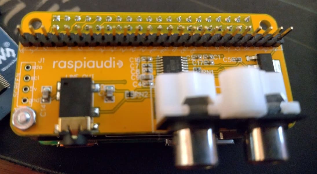
Hi there,
First off, the instructions on the install page worked perfectly for audio. Excellent work! I bought this a couple of months ago before the V3 was available.
I’m working on attaching an SPI screen to my streamer and I’m having issues on working out what the MOSI and MISO pins are connected to. I’m assuming that:
CE1 → GPIO7
CE0 → GPIO8
MISO → GPIO9
MOSI → GPIO10
CLK → GPIO11
which is SPI0.
The diagram on the install page doesn’t exactly match up with what my boards silkscreen has printed on it. For instance, the page’s pinout says on the 25-pin connector that the left most two pins are SDA an SCL, while on the board it says GND and 3V3.
Link to Installation Page Diagram
I’m guessing at some point the GPIO mapping got changed on the boards. Would it be possible to post the updated mappings so I may use the remaining pins on with my screen correctly?
Regards,
Dani

