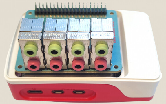
I have been working on a compact Raspberry Pi 5 setup that gives CamillaDSP direct access to 8 analog inputs and 8 analog outputs from one HAT. The idea is to make a small Linux DSP box for things like:
I put the installation notes, configs, and tests here:
Current tested setup:
Raspberry Pi 5
64-bit Raspberry Pi OS
CamillaDSP 4.1.3
ALSA device: hw:CARD=sndrpihifiberry,DEV=0
8-channel capture available
8-channel playback available
validated config: 48 kHz, 8 channels, S32_LE
direct ALSA access, avoiding PipeWire remixing/conversion
systemd service for running CamillaDSP at boot
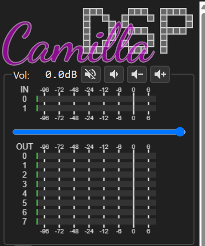
The default CamillaDSP config is intentionally boring: input 1 to output 1, input 2 to output 2, etc. I wanted the first public test to prove the basic audio path before adding FIR filters, crossovers, delays, or EQ.
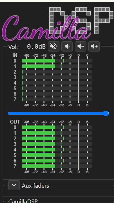
One loopback test uses CamillaDSP itself as the signal source. With a stereo cable connected on the second jack pair, CamillaDSP generated a 500 Hz signal on output channels 2 and 3, and the strongest captured signal came back on input channels 2 and 3, as expected.
Product page for context:
Separate 8-output-only board, not the board used in this CamillaDSP 8-in/8-out test:
This is great news ! Congratulations on such great work !
I wonder if a possible next step could be to be able to transfer all 8 channels of audio TO a PC via USB, using UAC 1.0 or 2.0.
I know very little about all these technologies, but someone in Github has been connecting Camilla DSP and a PC using UAC ( although in the other direction: the multichannel audio flows from the PC to the raspberry). This person wrote “Starting from Linux 5.18, UAC2 Audio gadget code is completed. When used with CamillaDSP, it is possible for a low power device such as Raspberry Pi 4 to be programmed to behave like a UAC2 device, which takes audio data from a computer, processes it, and sends it to an external DAC via USB.”
Please allow me to ask a dumb question ( because I get easily confused).
When we say “2ch USB-in and 8ch out” does it mean
A) 2ch INTO THE PC from the card, plus 8ch out FROM THE PC TO the card’s output jacks?
or it it
B) 2ch USB TO THE CARD output jacks FROM THE PC, plus 8ch FROM THE CARD’s input jacks INTO THE PC ?
The reason for this clarification is that I have been dreaming for a long time to use Raspiaudio hat to connect -via USB- a guitar TO a PC, so that I can record/process the 6 strings as 6 separate audio channels in the PC, so I need to move INTO the PC at least 6 channels of audio. Some guitars nowadays have an internal speaker, so the 2 channels FROM the PC TO the raspiaudio card could be used for the guitar internal speaker, after having applied VSTs, effects,etc.in the PC.
I know that most users would prefer to move 8 channels of data in the other direction, namely they would want 8 channels from the PC to the card, in order to connect 8 speakers and have 3d-spatial sound. But in my case I need data to move in the other direction.
PC → USB → Raspberry Pi / CamillaDSP → 8 analog outputs
So the PC sends 2 audio channels to the Pi, and CamillaDSP can process/split them to 8 analog outputs, for example for active crossover use.
What you describe is the opposite direction, more like a USB audio interface:
8 analog inputs from the 8xIN+8xOUT → Raspberry Pi → USB → PC/DAW
and optionally:
PC stereo output → USB → Raspberry Pi → 2 analog outputs
This should be technically possible with the 8xIN+8xOUT, by creating a different USB Audio Gadget profile, for example 8-channel capture + 2-channel playback. From the PC point of view, it would appear as a USB audio interface with 8 recording inputs and 2 playback outputs.
It is not the mode documented in this tutorial yet
Small update: we also tested an optional optical S/PDIF / TOSLINK output on Raspberry Pi 5.
CamillaDSP can now send stereo audio to a new ALSA device called RASPISPDIF. The Pi 5 generates the S/PDIF signal on GPIO12 using RP1 PIO + DMA.
In the first lab test, we simply used a standard LED on GPIO12 and placed a TOSLINK cable in front of it. A TOSLINK receiver/DAC locked and played clean audio. For a real product, we will use a proper TOSLINK transmitter socket, but no extra S/PDIF audio chipset is needed for optical output.