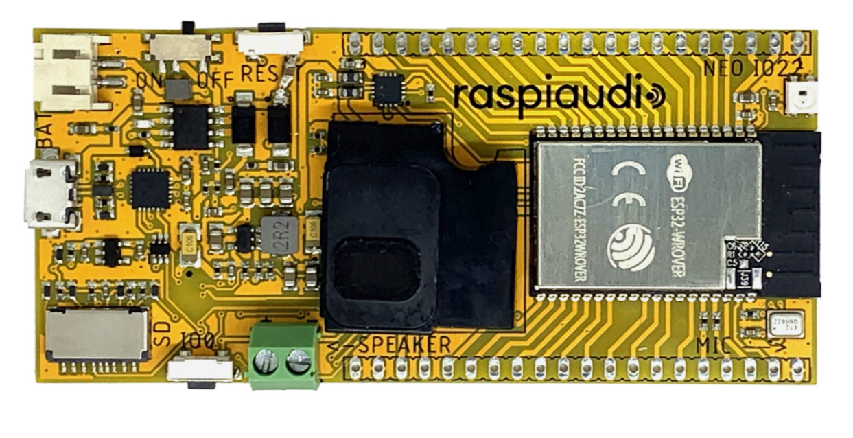
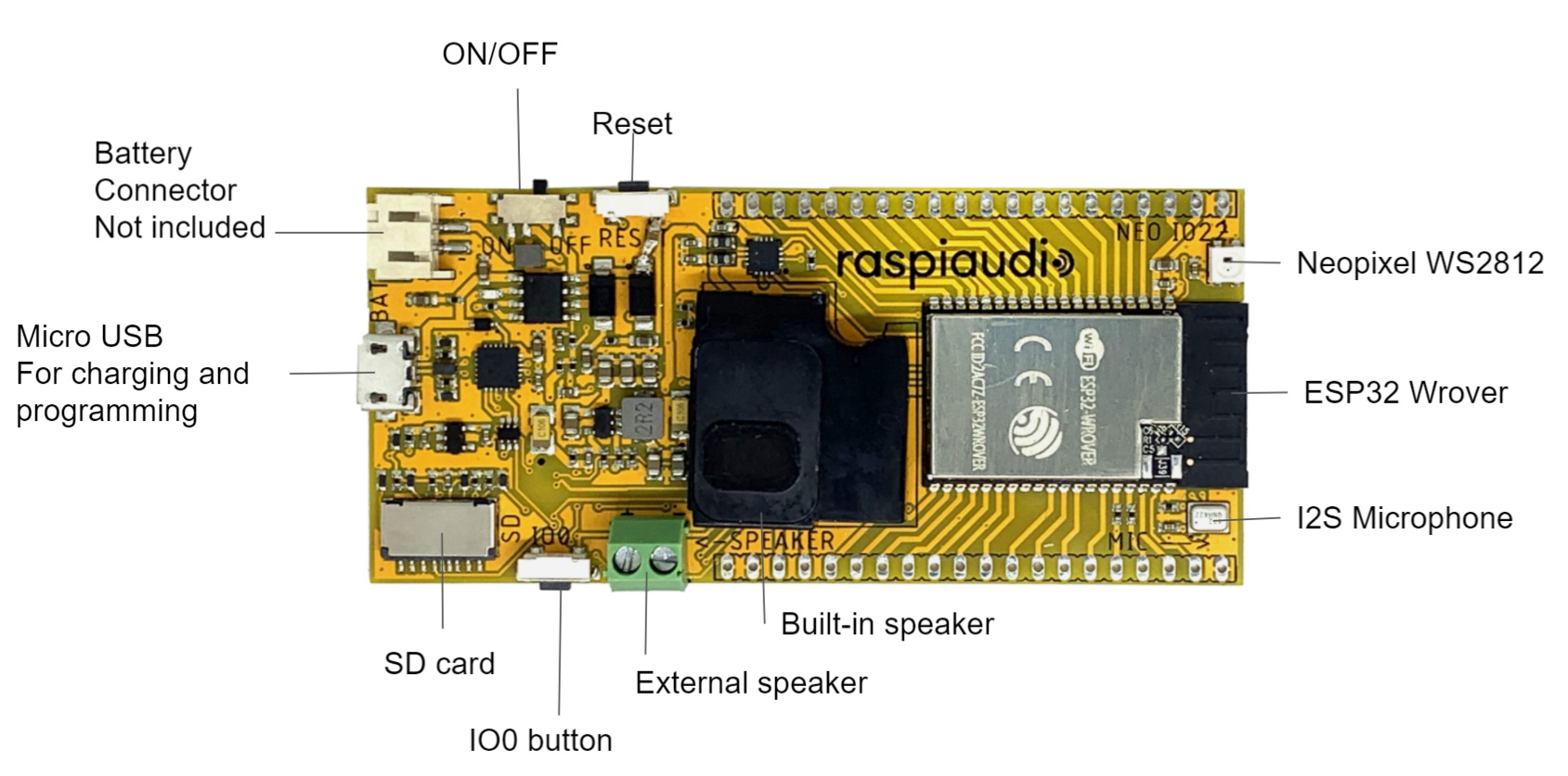
I have made this board for projects where you need to have an affordable protable audio solution, just power it and you will be able the stream audio with the built-in speaker or record.
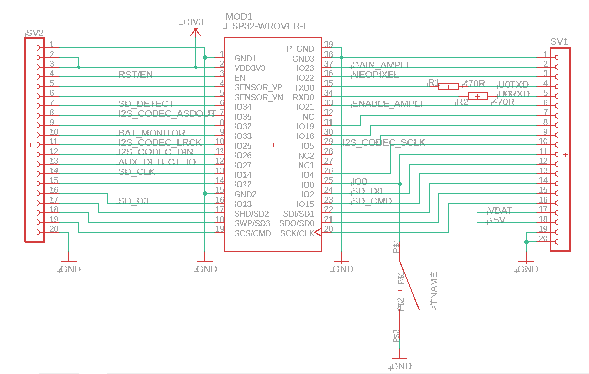
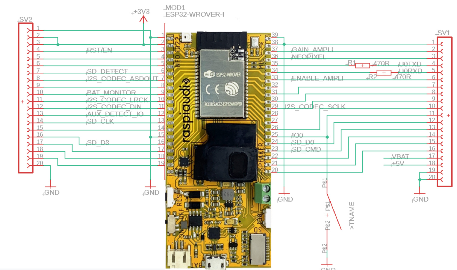
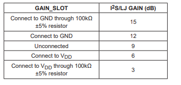
IO23 set the gain of the codec
for 15db you can use the internal resistor of the ESP32 (Output_pulldown)
for 3db (output_pullup)
IO21 enables (true) the amplification
programme it
note that you should remove any SD card from the SD slot before programming, or it will not self reboot
The board can be programmed using the Arduino IDE, you can follow this tutorials here :
Everything that could be expected from a commercial bluetooth speak but 100% hackable! Simple Bluetooth speakers
Hi, I’m testing my MuSE proto board, and I’m trying to get a little bit more “power” in the output.
I’ve seen There is an input battery and an output for speakers, as well as a cut here to disable onboard speaker.
Is there any way to get more output power with this board?
Glad that there is a first question about this board I’ve made
You can increase the volume on the speaker by initializing the gain of the codec in output pulldown for 15db
check the code of the radio or the bluetooth speaker:
If this is not enough plug a bigger speaker on the green terminal screw (this is optional to cut the trace behind the board to disable the built in speaker).
Connecting the battery should not make the volume louder.
I’m interested in getting one or two of these. Do you have any idea when they’ll be available to purchase again?
And while I’m waiting, can you confirm a couple of details?
Can you provide the board dimensions?
Can you confirm that the battery charging port is for a single Li-ion cell? If so, I assume I can make a parallel battery pack, provided I include some sort of balancing/protection circuit. Do you know the likely maximum current draw of the board?
Hi Chill
It is available on in Amazon Europe and USA, but not in the UK for a while
Yes the battery is for one cell 3.7v Li ion yes you can put as much cell in parallel as you want. There is no need of balancing with 1S pack. The charging circuit already provides over charging, over discharge, and over drawn protection. But indeed I also use myself battery with an extra protection. Max peak consumption is 2A.
For dimensions we will add them Friday I’m off it of the office.
Hi - I am assembling a battery pack for use with a Muse Proto. Can you please confirm what type of plug is required to connect to the battery charging port?
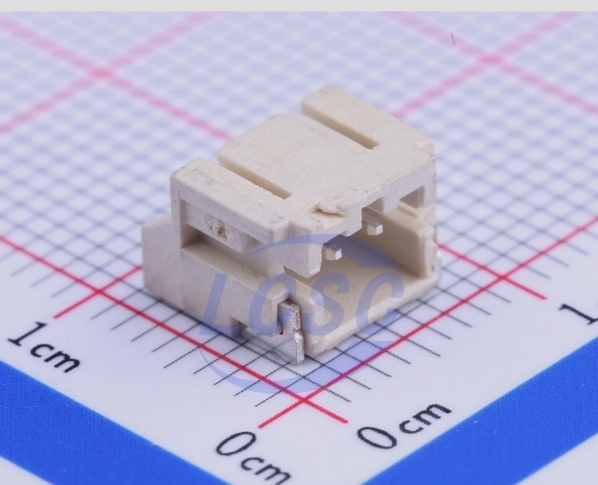
Alas, no - only 3 and 4-pin versions. Forgive me - I’m only going from pictures, since my Protos haven’t arrived yet, but the socket does not appear to be compatible with the battery plug that I’m familiar with - the one with the two arrow-shaped guides that latch into the socket - JST-XH?
Can you please confirm which JST series I should look for?
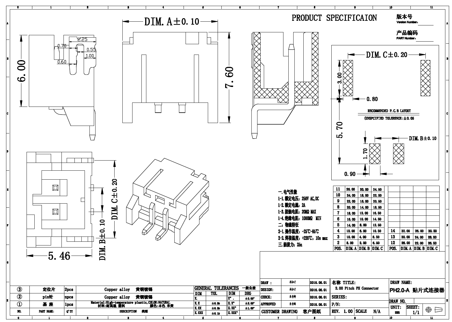
This look like that, but to be honest I’m not exactly sure of what JST serie it is, just know it’s just 2mm pitch.
Maybe I should include a cable in the package in the future
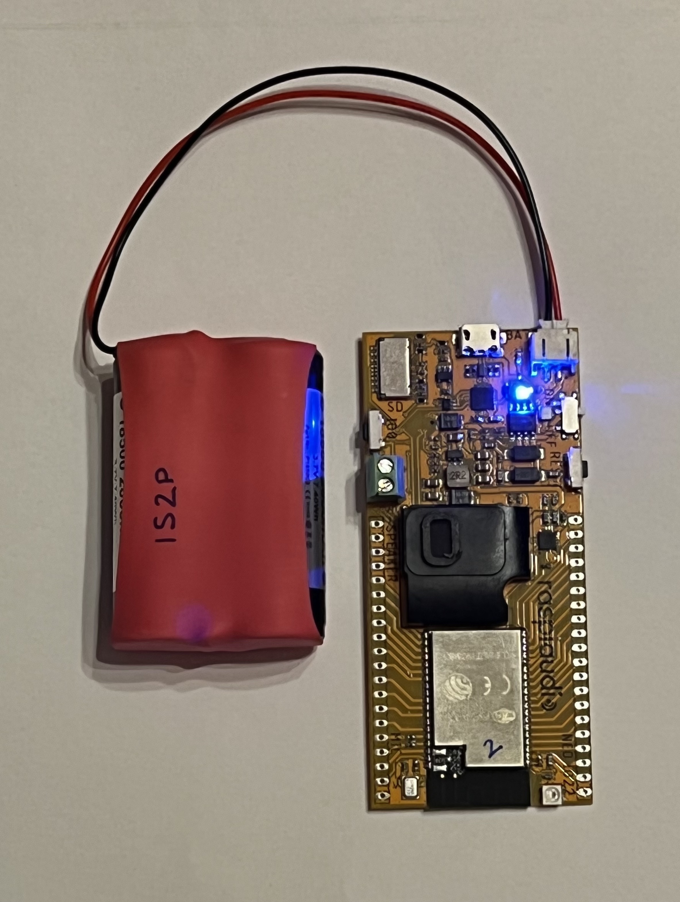
Thank you. I purchased some pre-wired JST PH connectors (here). They are wired with the opposite polarity to the connector on the board (thank you for the ‘+’ and ‘-’ symbols on the PCB!), but I simply swapped the terminals in the housing. So now it works fine on battery power alone.
Next question - is there a convenient place to solder onto to provide the 5V input, if I don’t want to use the on-board micro USB socket? I cannot see anywhere convenient, except maybe if I remove the USB socket altogether, but I thought I’d check here first.
I assume that if I soldered onto, say, the 5V pin on the edge of the board, that would not back feed the battery charging circuit, for instance.
Nice
No the 5v pin (out of the battery booster) is different from the VBUS of the USB.
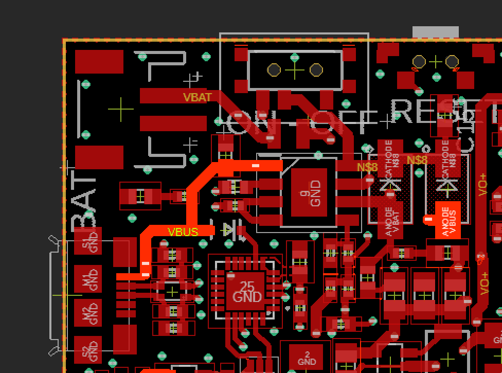
if you would liket to solder something on the VBUS you can locate it on the bright red track here:
Thank you! The anode of that diode seems to offer the best option for soldering a small wire, but I’m not sure that I want to do that. It was just an idea to connect the board to a separate USB socket - I am thinking I will build the Proto into an enclosure to make a portable Squeezebox player, but connecting a micro USB plug into the on-board socket will increase the required size of the cavity that the board will fit inside.
Yes, my experiments with the battery pack have been safe - my 1S2P battery pack has protection against overcharge, overdischarge, short circuit and overcurrent (this PCB)
Maybe not related but for charging I like having a magnetic usb in the micro usb so it easier to connect it and prevent mechanical stress on the usb port :
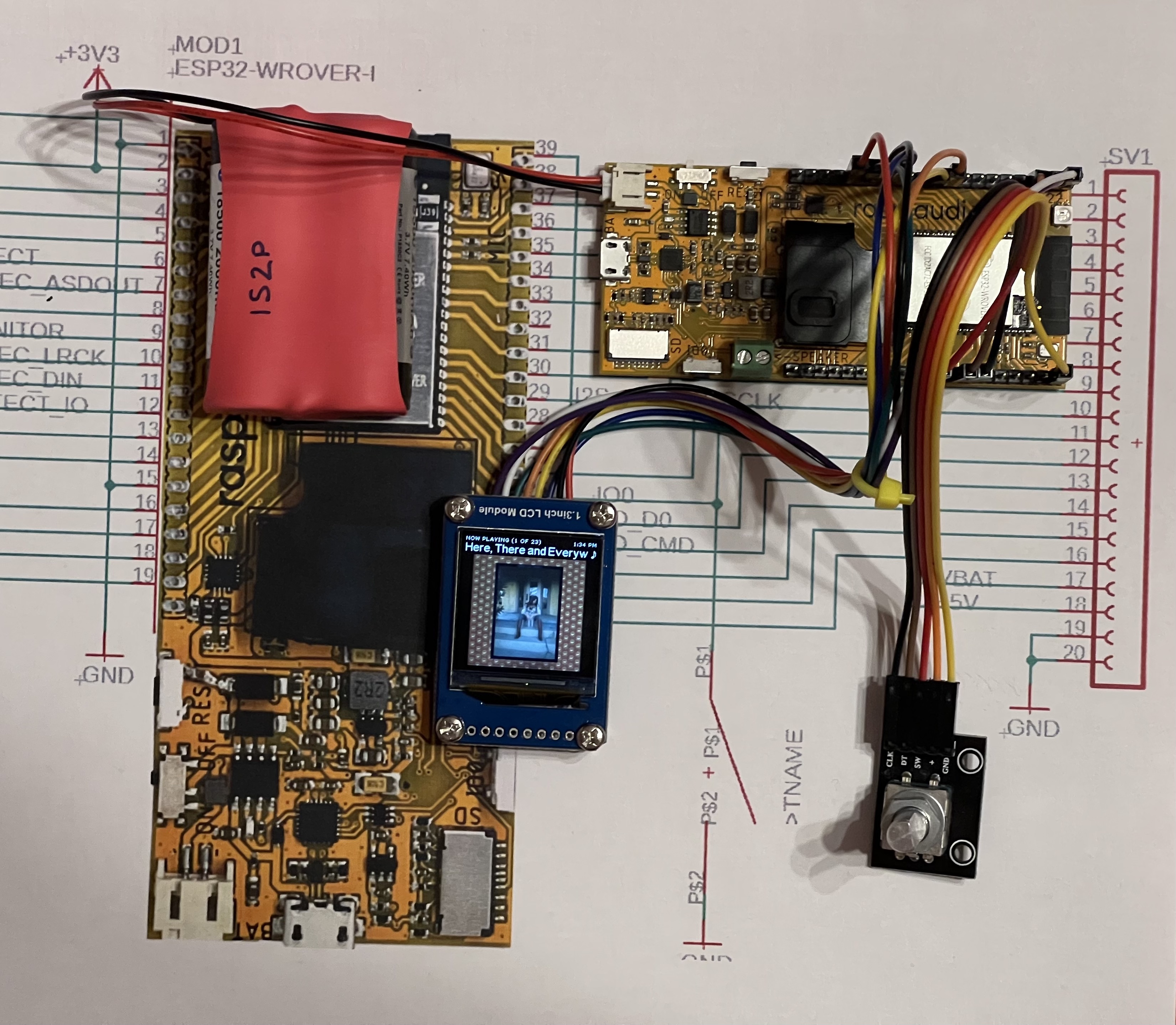
I’ve been experimenting with this board for a few days. I really like it. I’ve loaded your SqueezeESP .bin file and updated it over-the-air to the latest standard SqueezeESP. I’ve added a display and a rotary encoder.
I’m pleasantly surprised by the quality of the on-board speaker. Do you have any further information about it? A spec sheet perhaps? I’m curious whether an enclosure of some sort might improve it still further, so it would be interesting to see what the manufacturer suggests. I can see that there’s a rubber gasket on the top surface, so maybe a sealed enclosure around the module will help. Probably an airtight enclosure will not be possible, due to the various ports on the board, but some sort of partially sealed 3D-printed enclosure could be possible.